RPLIDAR A3M1
RPLIDAR A3M1 is a 360 degree 2D LIDAR developed by SLAMTECH. It can perform 2D 360-degree scan within a 25 meter range and generates 2D point cloud data that can be used in mapping, localization and environment modeling. It is based on laser triangulation ranging principle. It supports to work under two modes: enhanced modes and outdoor modes. The enhanced mode of RPLIDAR is being used in our Racecar project for point cloud visualization and object detection.
Sample Point Data Information
During working process, the RPLIDAR will oputput the sampling data and each sample point data contains the information as mentioned in the foloowing table:
Data Type |
Unit |
Description |
|---|---|---|
Distance |
mm |
Current measured distance value between the rotating core of the LIDAR and the sampling point. |
Heading |
degree |
Heading angle of the measurement |
Start Flag |
Bool |
Flag of new scan |
Checksum |
Checksum of LIDAR return data. |
Measurement Performance Specification
Item |
Enhanced Mode |
Outdoor Mode |
|---|---|---|
Operating Range |
White object: 25 meters, Black Object: 10 meters |
White object: 20 meters, Black Object: TBD |
Minimum Operating Range |
0.2m |
0.2m |
Sample Rate |
16 kHz |
16 kHz or 10 kHz |
Scan Rate |
Typical value: 10 Hz (adjustable between 5 Hz - 15 Hz) |
Typical value: 10 Hz (adjustable between 5 Hz - 15 Hz) |
Angular Resolution |
0.225 degree |
0.225 degree or 0.36 degree |
Communication Interface |
TTL UART |
|
Communication Speed |
256000 bps |
Coordinate System Definition of Scanning Data
The RPLIDAR uses a left-hand coordinate system. The x-axis is directly ahead of the sensor, and origin is the rotating center of the range scanner core. The rotation angle increases in clockwise direction. The deatailed is shown in figure below:

Communication Interface
It uses separate 5V DC power for powering the range scanner core and the motor system using XH2.54-5P male socket. The details interface is illustrated in the figure and the description of the same can be found in the table below:
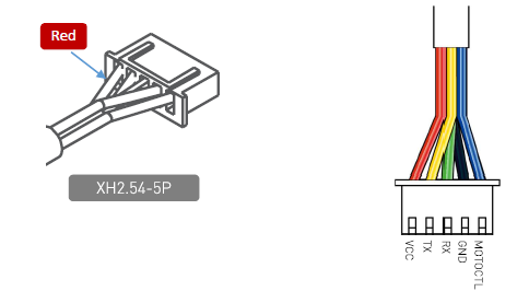
Color |
Signal Name |
Type |
Description |
Min |
Typical |
Max |
|---|---|---|---|---|---|---|
Red |
VCC |
Power |
Total Power |
4.9V |
5V |
5.2V |
Yellow |
TX |
Output |
Serial port output of the scanner core |
0V |
3.3V |
3.5V |
Green |
RX |
Input |
Serial port input of the scanner core |
0V |
0V |
0V |
Black |
GND |
Power |
GND |
0V |
0V |
0V |
Blue |
MOTOCTL |
Input |
Scan motor / PWM Control Signal |
0V |
3.3V |
5V |
Serial Port Interface Specification
Item |
Unit |
Min |
Typical |
Max |
Comments |
|---|---|---|---|---|---|
Band Rate |
bps |
256000 |
|||
Working Mode |
8N1 |
8n1 |
|||
Output high voltage |
Volt (V) |
2.9 |
3.5 |
Logic High |
|
Output low voltage |
Volt (V) |
0.4 |
Logic Low |
||
Input high voltage |
Volt (V) |
1.6 |
3.5 |
Logic High |
|
Input Low voltage |
Volt (V) |
-0.3 |
0.4 |
Logic Low |
Specification for PWM Signal of MOTOCTL
The roatting speed for the motor of LIDAR is controlled via MOTOCTL which is supplied using PWM signal with special frequency and the speed of the motor is decided by the duty cycle of the input MOTOCTL PWM Signal. The rerquirements for the input PWM Signal of MOTOCTL is described in the table below:
Item |
Unit |
Min |
Typical |
Max |
Comments |
|---|---|---|---|---|---|
High Level Voltage |
V |
3.0 |
3.3 |
5 |
|
PWM Frequency |
Hz |
24,500 |
25,000 |
25,000 |
Square Signal |
Duty Cycle Range |
0% |
60% |
100% |
Typical value is the duty cycle of high pulse wodth when the scannner frequency is at 10Hz |